Integrated Gear Design


Integrated Gear Design
IGD – Integrated Gear Design –
is a powerful and comprehensive computer program for gear design, analysis, optimization and troubleshooting of gear drives.
It integrates a virtual gear generator with algorithms for tooth contact analysis, backlash analysis, free-form design and automatic generation of finite element models for stress analysis. IGD is the tool to be used when noise, vibration, life, or endurance are key factors to be considered for existing or new gear drives.
IGD has been developed thinking of both advanced gear design and gear manufacturing. The virtual gears can be generated by virtual cutting tools mimicking the corresponding manufacturing processes. The gear models generated by IGD can be exported to main CAD/CAE computer programs in IGES, OBJ or STL graphics formats.


Main Features
The main features of IGD are:
- Virtual gear generator of almost any type of gearing
- Free-form design module for all types of gearing
- Compensation of errors of alignment or deflections at the design stage
- Tooth contact analysis (TCA) based on three pairs of contacting teeth
- Finite element models ready to run in main commercial FEA computer programs
- Finite element models including gears, shafts, and bearing
- Simulation of manufacturing errors and their effects on contact patterns and contact and bending stresses
- Comparison of gear geometries
- Design of flank edge coordinates.
- Backlash analysis all over the cycle of meshing
- Gear geometry export capability for additive manufacturing
- Postprocessing performance of actual gear geometries based on point clouds obtained by non-contact metrology
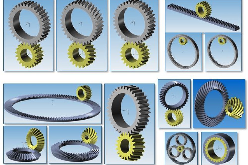
Gear Sets
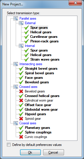
IGD has been developed considering the extension of its capabilities to all types of gear sets. The gear set types implemented in the latest version of IGD are shown on the right side figure by means of a green mark. The gear set types that are pointed by means of a red X-shaped mark will be implemented in the near future.
The gear set types are organized considering the arrangement between the gear axes into the following three categories: Parallel Axes, Intersecting Axes, Crossed Axes, and Coaxial Axes.
- Parallel Axes gear set types are organized into two groups: External and Internal.
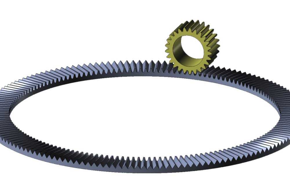
- Parallel Axes - External gear set types include spur, helical, curvilinear, and pinion-rack gear sets.
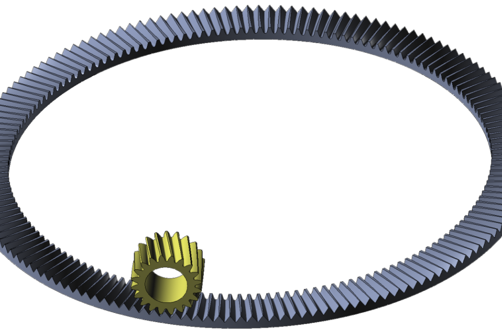
- Parallel Axes - Internal gear set types include spur, helical gear sets. The strain wave gears are a work in progress now.
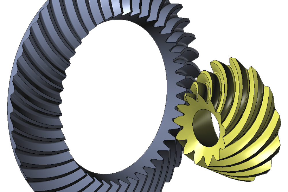
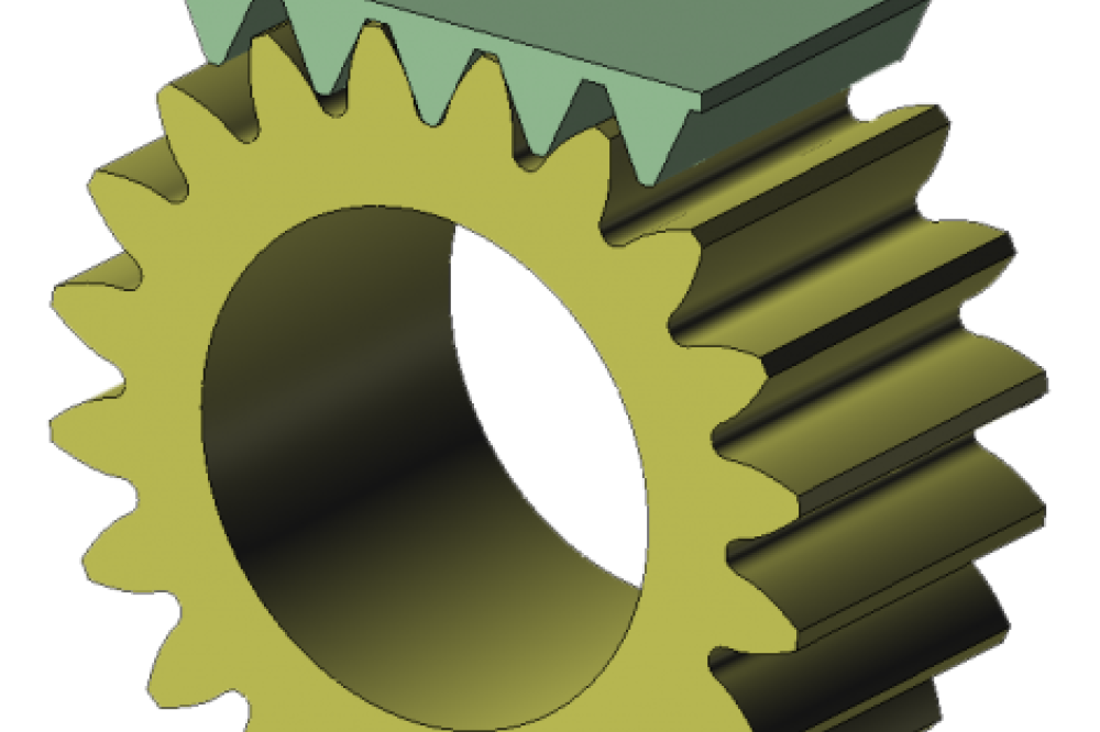
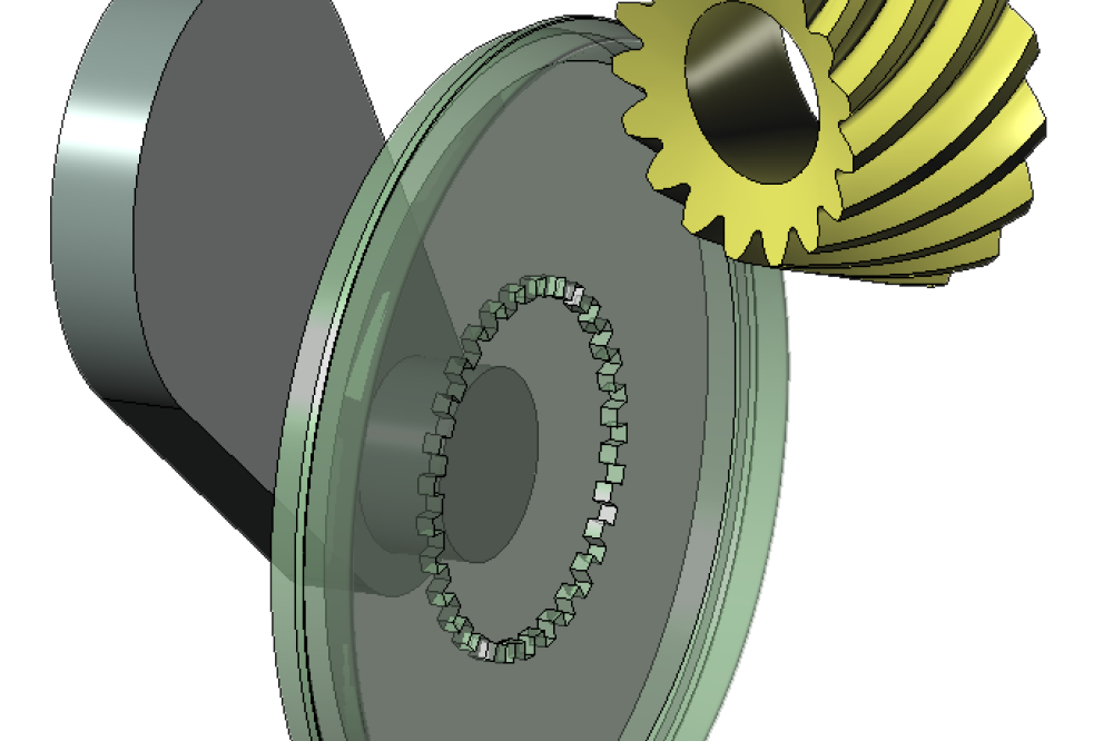
- Intersecting Axes gear set types include straight bevel, spiral bevel, face gear, and beveloid gear sets.
- Crossed Axes gear set types include crossed helical, offset face gears, globoidal worm and hypoid gear sets.
- Coaxial Axes gear set types include planetary gear sets and spline couplings.
Parallel axes: external


Parallel axes: internal


Intersecting axes


Crossed Axes


Coaxial Axes


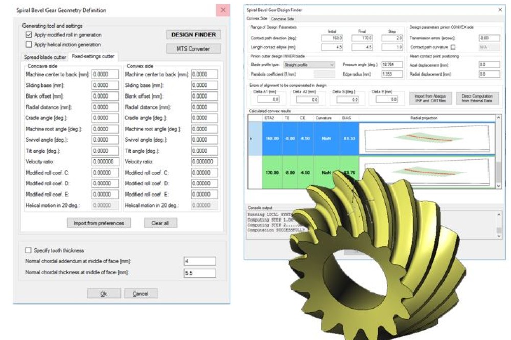
Generating Tools
IGD implements a variety of generating tools for every type of gear. Straight, parabolic, or circular profiles can be considered for the generating tools, allowing tip and root reliefs to be provided in order to improve the process of tooth loading and unloading during the cycle of meshing. Root and tip reliefs are fundamental to minimize contact stresses along the cycle of meshing. The blades of the generating tools are designed considering not only the active part but also the blade edge that will generate the fillet of the gear teeth, allowing the accurate determination of fillet stresses.
Profile Types
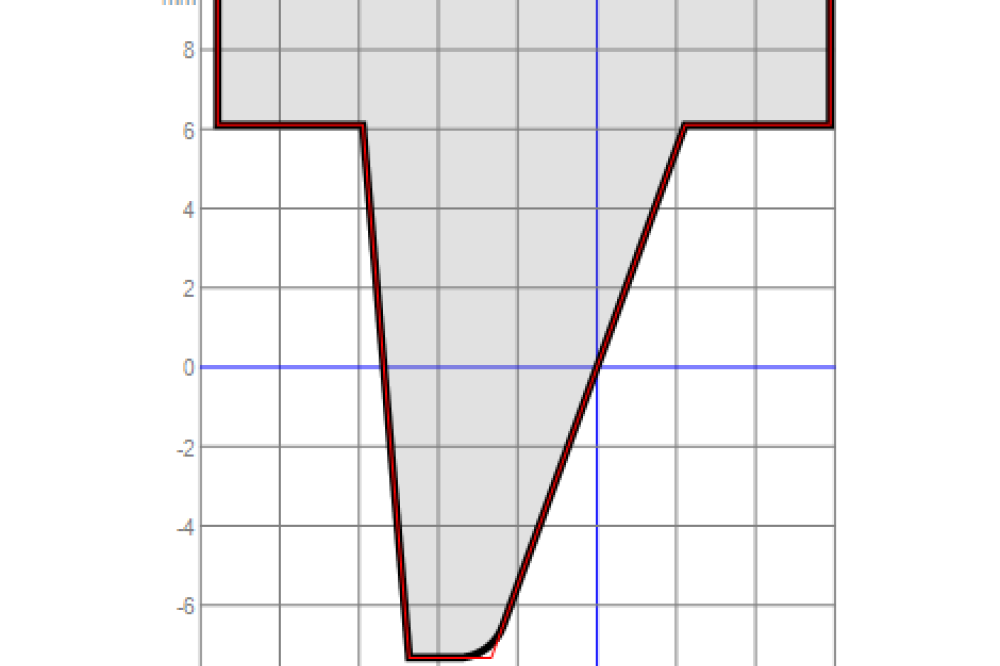

Gear Generating Tools


Analyses
The analyses that can be carried our in IGD are arranged in two main groups:
- TCA & FEM analyses: Tooth Contact Analysis and Finite Element Modeling
- GEO-Comp analyses: Comparison of gear geometries
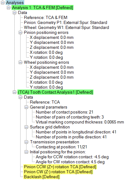
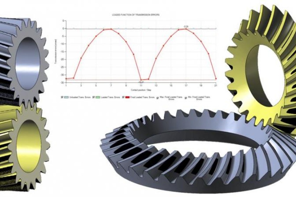
Tooth Contact Analysis (TCA)
Tooth Contact Analysis (TCA) involves: (i) the determination of the contact pattern and the contact path on the gear tooth surfaces, (ii) the determination of the function of unloaded transmission errors, and (iii) the determination of the function of backlash. These results are obtained considering the following user data:
- The selected pinion and wheel geometries
- The positioning errors of pinion and wheel in the gear set
- The number of pairs of contacting teeth: One or Three
- The number of contact positions along one or two cycles of meshing
- The virtual marking compound thickness for an estimation of the size of the bearing contact under light load
- The direction of pinion rotation: counterclockwise or clockwise
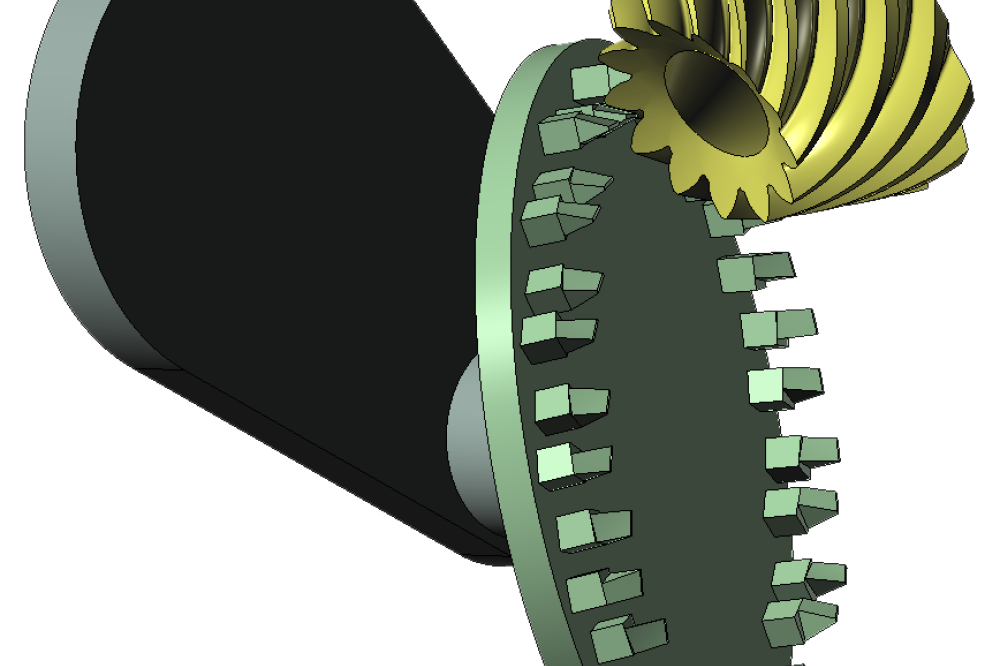
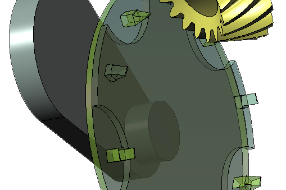
A general-purpose algorithm for tooth contact analysis is applied for computerized simulation of gear meshing and contact pattern estimation. It is based on a numerical method that takes into account the positional study of the tooth surfaces, which are discretized by means of a grid definition, and minimization of the distances until contact is achieved.
Examples of results that can be obtained from our TCA are shown below for a spiral bevel gear set, a planetary gear set, and a spline coupling. Application of TCA in a planetary gear set requires the determination of the contact patterns between the sun gear and each planet gear, and between each planet gear and the ring gear. A spline coupling requires just one contact position since all pairs of teeth can be simultaneously in contact.


Tooth Contact Analysis (TCA)
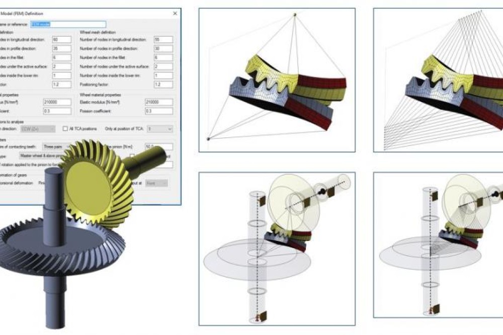
IGD allows the preprocessing of the finite element model of the gear set for the investigation of its mechanical behavior. Different types of finite element models are supported in IGD. Those FE models can be exported to Abaqus or Ansys for further analysis. The main features of the finite element models that can be generated in IGD are as follows:
- The user has a complete control on the number of elements to be considered on the tooth surfaces, under the tooth surfaces, and inside the rim. The nodes located on the tooth surfaces are points generated from the virtual gear generator or from the free-form design tool
- The finite element models are all set for the FE analysis at a chosen contact position or for the FE analysis along one or two cycles of meshing. The finite element models consider the direction of rotation of the pinion (counterclockwise or clockwise), and one, three, five or seven pairs of contacting teeth
- The fillet surfaces can be considered as contacting surfaces for detection of interferences
- The load is directly applied to the pinion by means of the transmitted torque while the rotation of the gear (wheel) is blocked. No assumptions of load distribution are required
- The torsional deformations of gear tooth surfaces can be considered in the finite element models
- Shaft deflections can be considered by adding the shafts to the finite element models. IGD incorporates a design tool for shafts that allows the definition of the dimensions (length and diameter) for each section of the shaft, the location of the gears, and the location of the bearings


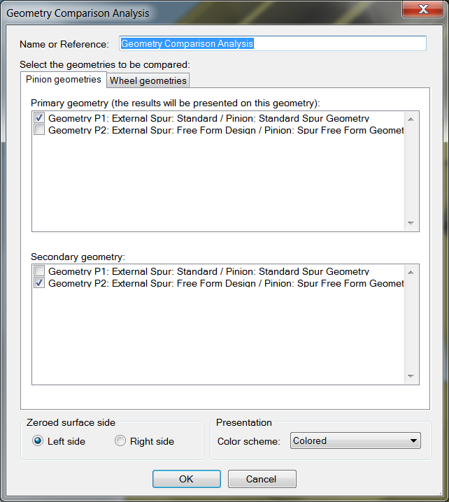
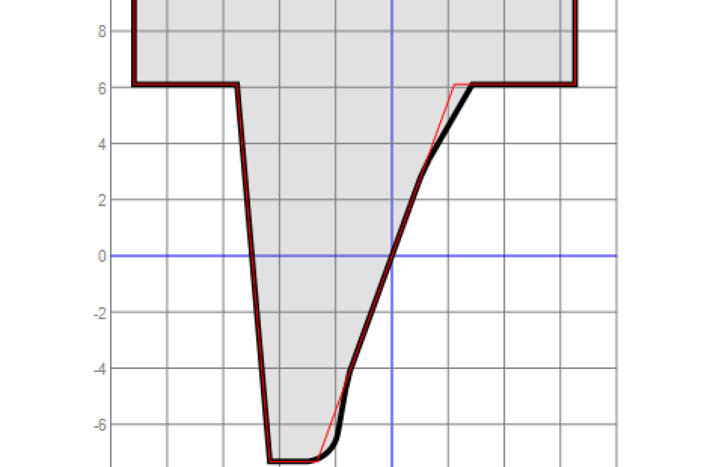
Comparison of Gear Geometries (GEO-Comp)
GEO-Comp analyses allow the comparison of gear geometries through the determination of the distances between the corresponding gear tooth surfaces. The geometry comparison analysis requires selection of the geometries to be compared and the reference side (left or right) for comparison. One of the geometries is considered as primary geometry whereas the other one is considered as secondary geometry. The tooth surfaces of the selected geometries are brought into contact at the reference side for comparison (left or right). The results of the comparison are the distances between the primary and the secondary gear tooth surfaces, measured in the normal direction to the primary gear tooth surfaces. The results of comparison are illustrated on the primary tooth surface. GEO-Comp analyses allow independent comparison at left and right sides, or combined comparisons where results on both sides will be simultaneously shown.


IGD Tutorials
Project-Based Learning IGD - Tutorial #1
This tutorial is directed to evaluate the increment in contact and bending stresses in a spur gear drive, comprising a pinion of 21 teeth and a gear of 34 teeth and module of 3 mm, with no surface modifications and subjected to an error of alignment of 0.05 deg. in the crossing angle by using IGD - Integrated Gear Design.
Project-Based Learning IGD - Tutorial #2
This tutorial is directed to the determination of the optimal tip relief in a helical gear drive comprising a pinion of 24 teeth and a gear of 37 teeth. The gears have a module of 4 mm, a helix angle of 15.0 deg, a pressure angle of 20.0 deg, and a face width of 35.0 mm. The torque applied to the pinion is 800.0 N·m. The gears will be mounted at the reference center distance of 126.304 mm. IGD v3.5 is used for gear geometry generation and tooth contact analysis. Stress analysis is performed with ABAQUS and results postprocessed within IGD.