DIRSIG Support to Arete for the US Navy Coastal Battlefield Reconnaissance and Analysis (COBRA) System
Project Description
This work is an ongoing, follow-on project to an SBIR/STTR (N19A-T010) Phase II Option to extend DIRSIG's maritime modeling capability to lidar. Initial work under that program developed a baseline capability to model the interaction of a green bathymetric laser with models of wind-driven water surfaces, distributions of in-water constituents, bottom surfaces and objects embedded fully or partially within the water. That capability is used to drive simulated data products based on a model of Arete's commercial streak tube imaging lidar (STIL) system or other similar systems. The current work has focused on maturing the model through more robust radiometric calculations, testing, and feedback from the Arete team as the model is compared to real world data.
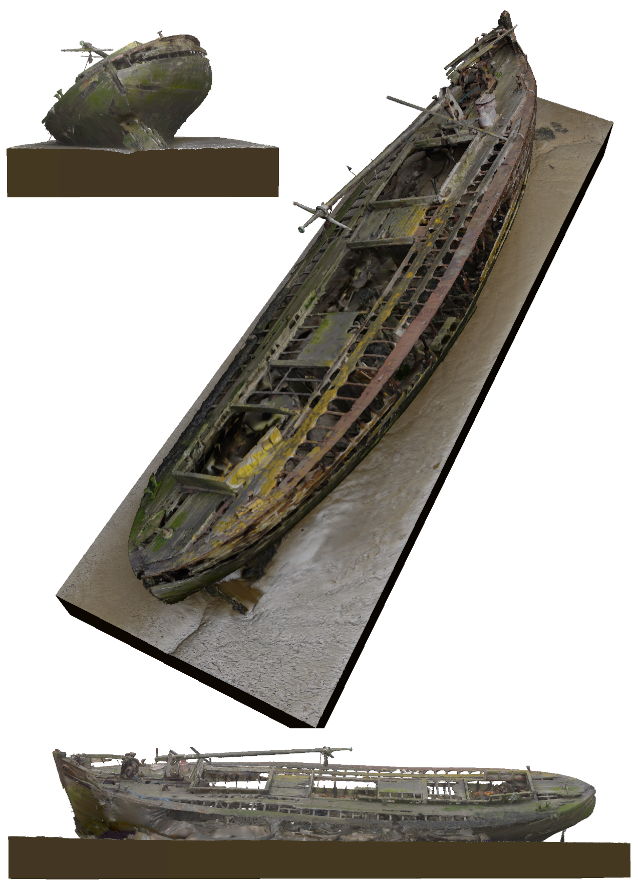
Figure 1: Geometry for a submerged shipwreck based on a 3D scan of a wooden barge wreck off of Frobisher Way, Greenhithe, Kent UK. The single along-track "slice" shown in the accompanying figure is across center of the boat, including the folded mast. "Greenhithe Barge Wreck" (https://skfb.ly/oSwQU) by artfletch is licensed under Creative Commons Attribution (http://creativecommons.org/licenses/by/4.0/).
Simulation of a laser pulse in any environment requires the careful handling of the pulse energy distribution in both space and time. The modeling of an active lidar system interacting with water posed new challenges for DIRSIG.
First, the air-water interface is constantly changing, particularly from pulse-to-pulse. While the interface itself has a negligible effect on the return signal most of the time, when there is perfect alignment with the surface slope and the incident pulse, the resultant retro-reflection is usually the strongest signal. We have developed an efficient means of searching the geometric representation of the continuous wind-driven surfaces being intersected by the pulse. That allows us to find (usually extremely small and sparse) "patches" of those surfaces that happen to be aligned such that they will reflect the laser pulse back to the effective aperture of the receiver system. We have also improved our ability to model the surfaces themselves, attempting to find the best ways to capture the slope and height diversity in real water surfaces that drives those returns -- a difficult prospect when the most common drivers are on the order of centimeters (e.g. capillary waves) and the scene model must capture 100s of meters of water surface.
Second, once the pulse enters the water, it is continuously being scattered in every possible direction by the organic and inorganic particulate matter within the water as well as the water itself, often 10s or 100s of times. In a manner that is similar to the way we handle the passive modeling of sun and moon light interacting with the water, we take a bi-directional approach, modeling the forward propagation of the pulse into the water, tracking the (internally) unscattered path of the energy. Then, a backwards (from the receiver) ray generation process finds individual (multi-)scattered paths that connect to that primary path. The work under this program has not only improved this approach, but has added numerous ways for the user to observe individual components of the calculation and separate the solution by scatter order.
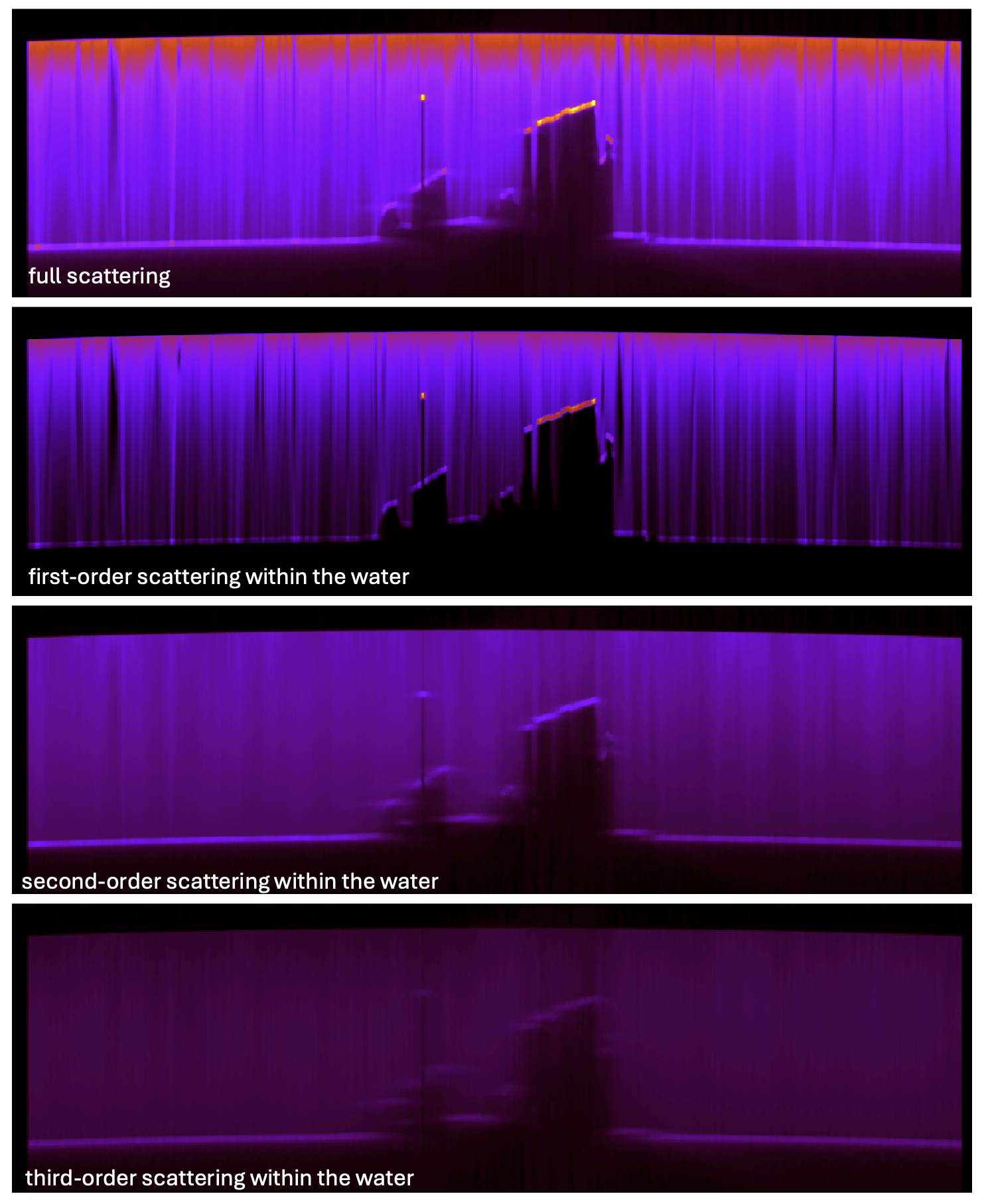
Figure 2: Output from a (fictional) high spatial-definition STIL-like system observing a single collection of the center of a submerged shipwreck. Each image shows the across-track spatial dimension for the horizontal axis while the vertical axis is the temporal dimension (increasing from top to bottom). The shipwreck model was placed under a water surface with calm (very light breeze) conditions so that the ship structure is apparent. The top image represents the simulation of the real-world product while the three additional images break the signal up by scattering order (all on the same visual scale). Note that returns can appear to come from within solid objects due to the temporal ambiguity that results from scattered light.
The remainder of the project time will be used to further verify the model against real world data and improve the user experience. It will give us a new capability in DIRSIG backed by a novel modeling approach and real world data.